A while ago now I wrote an article for the UKHAS website on linking an NTX2 to the Arduino. This tutorial, available here : http://ukhas.org.uk/guides:linkingarduinotontx2 is still valid however there are other ways to modulate the NTX2 or the NTX2B to get RTTY.
In part 1 of this article I’ll discuss using PWM to generate the required voltages to modulate the NTX2B, the physical wiring, how to test it and sample code. Part 2 will extend this to transmitting RTTY and finally part 3 will discuss using this to transmit DominoEX.
Please follow this entire article the basic code allows you to demonstrate step by step that your circuit is working.
Introduction
Getting your Arduino to transmit via the radio initially may seem daunting but its actually pretty simple. Please freely substitute the word “Arduino” for any micro-controller you wish to use. The example below works for 5V and 3.3V micro-controllers.
Please read this :
This may be the first bit of code you’ve come across with regards to creating a radio tracker. There is always the temptation to cut and paste it and away you go. And in isolation this may work. However should you then cut and paste further code without understanding what is going you will end up with an unworkable mess and something that is next to impossible for us to assist you with. Please take the time to work out what the code below is doing, redo it yourself, break it, fix it most importantly understand it.
Theory
You adjust the voltage on the NTX2’s TXD pin which adjusts its transmission frequency slightly. The difference in this frequency is called the shift. By doing this in a controlled fashion you can transmit 1’s and 0’s and therefore transmit meaningful data.
The NTX2 is a FM (Frequency Modulation) module intended to have a voltage applied to the TXD pin of between 0 and 3 volts. This voltage range changes the output frequency of the module by about 6KHz (i.e for a 434.200Mhz module 0V on TXD = 434.195Mhz and 3V on TXD = 434.202Mhz.
This means for each 1Hz change in frequency you need to change the voltage by 0.0005v (3 divided 6000) so to get a shift of 500hz you need to toggle the voltage applied to the TXD pin by 425×0.0005=0.2125v.
To get this voltage shift we are going to use PWM (Pulse Width Modulation). See this article for more information on PWM : http://arduino.cc/en/Tutorial/PWM. The resolution of this is 8 bits which means the Arduino can change the voltage by 256 (2^8) steps. This means the maximum voltage of 5V can be broken into 5/256 steps or 0.0195v per step. The maximum input of the NTX2B is 3V therefore there is no point applying voltages of greater than 3V. As a decimal this means 3/5* 256 = 153.
In theory the standard shift of 425Hz equates to a 0.2125/0.0195 = 11, however in reality on an NTX2B a value of 10 gave a perfect 425Hz shift. Don’t get too hung up on getting the exact shift, any shift from 350-500Hz is fine.
Items Required
Radiometrix NTX2B
Arduino or similar micro-controller
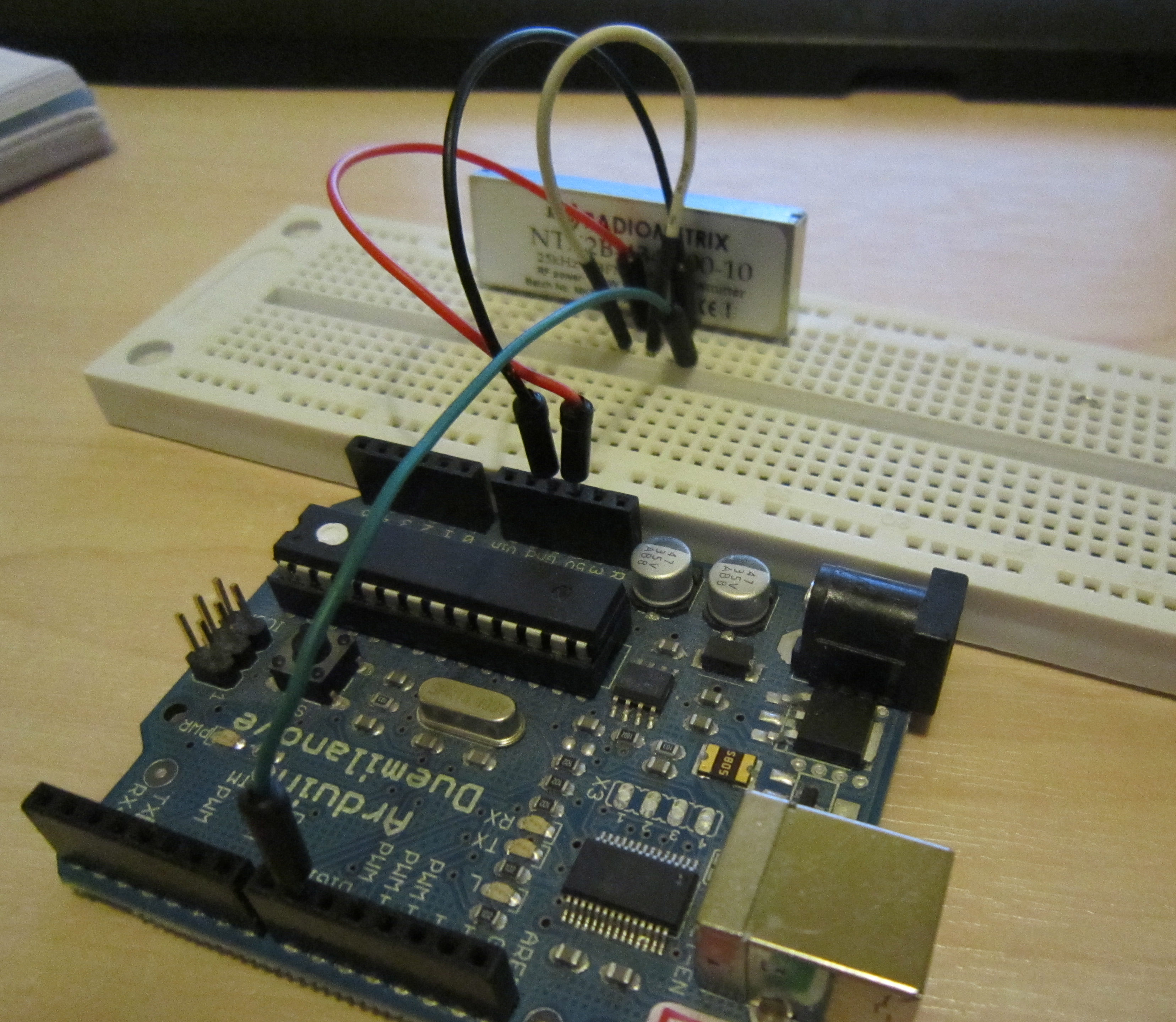
Circuit Diagram

Connect Arduino 5V to the NTX2B VCC pin 5
Connect Arduino 5V to the NTX2B EN pin 4
Connect Arduino GND to the NTX2B GND pin 6
Connect Arduino pin 9 to the NTX2B TXD pin 7
Once done it should look like this (you don’t need an antenna in at this point) :
The Code
The code is similar to the Fade example built into Arduino (File->Examples->03.Analogue->Fade)
|
1
2
3
4
5
6
7
8
9
10
11
12
13
14
15
16
17
18
19
20
21
22
23
24
25
26
27
28
29
30
31
32
33
34
35
36
37
38
39
40
41
42
43
44
45
46
47
48
49
50
51
52
53
54
55
56
57
58
59
60
61
62
63
64
65
66
67
68
69
70
71
72
73
74
75
76
77
78
79
|
/* Demo Code to Drive NTX2B via PWM Written by Anthony Stirk M0UPU This example code is in the public domain. */#define RADIOPIN 9void setup() { pinMode(RADIOPIN, OUTPUT); setPwmFrequency(RADIOPIN, 1);}void loop() { analogWrite(RADIOPIN,100); delay(500); analogWrite(RADIOPIN,110); delay(500);}void setPwmFrequency(int pin, int divisor) { byte mode; if(pin == 5 || pin == 6 || pin == 9 || pin == 10) { switch(divisor) { case 1: mode = 0x01; break; case 8: mode = 0x02; break; case 64: mode = 0x03; break; case 256: mode = 0x04; break; case 1024: mode = 0x05; break; default: return; } if(pin == 5 || pin == 6) { TCCR0B = TCCR0B & 0b11111000 | mode; } else { TCCR1B = TCCR1B & 0b11111000 | mode; } } else if(pin == 3 || pin == 11) { switch(divisor) { case 1: mode = 0x01; break; case 8: mode = 0x02; break; case 32: mode = 0x03; break; case 64: mode = 0x04; break; case 128: mode = 0x05; break; case 256: mode = 0x06; break; case 1024: mode = 0x7; break; default: return; } TCCR2B = TCCR2B & 0b11111000 | mode; }} |
Excluding the setPwmFrequency procedure (all this does is set the PWM speed as quick as it will go to made the voltage presented to the NTX2B PWM pin as more “analogue”) this code simply opens pin 9. It then alternates the voltage on this pin by 10 every 1/2 second. You can plug an LED into pin 9 to see what its doing.
Load this code up to the Arduino.
Ok now take your radio and tune it into the frequency of the NTX2B module. You should hear the high and low tones. If you’re using an RTL + SDR# set the frequency to something above the frequency of the module, i.e in this example our NTX2B is transmitting on 434.200Mhz so I’ve set SDR# to 434.500Mhz. You can see a peak on the left of the spectrum analyzer at the top around 434.200Mhz :
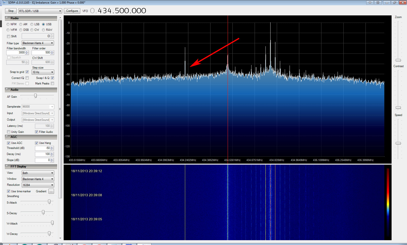
If you’re unsure if this is the radio, turn it off. It will disappear. Zoom in the line using the zoom on the right. You may want to increase the resolution in the FFT Display at this point, with a resolution of 262144 you should see some distinct high and low tones separated by about 425hz :

Congratulations you’re transmitting. If you’re ever unsure if your radio is working you should step back to this extremely simple code to check the basic operation. Now move to part 2 of this article to transmit some meaningful data : http://ava.upuaut.net/?p=627
Getting started with the NTX2B and the Arduino – Part 2 RTTY
In part 1 of this article I discussed linking the NTX2B to the Arduino and getting a high and low tone out of it. In this article we go one step further and turn this into a transmission of data.
Using the circuit discussed in the previous article upload the following code will transmit a short sentence at 50 baud, 7 bits ASCII 2 stop bits. Also the code adds a CRC checksum at the end of the data string.
The datastring variable is passed to a procedure called rtty_txtstring which takes care of transmitting the data by breaking it down into characters, then it transmits the individual bits of those characters. The key to getting the baud rate correct is the timing. Theoretically 50 baud should be 1/50th of a second = 20000µS however the Arduino delayMicroseconds command can only do a maximum delay of 16383µS. To get round this we do two delays of 10000µS.
300 baud after some playing seemed to be stable around 3370µS delay ( 300 baud should be 1/300s = 3333µS). You can uncomment the relevant lines out as needed.
|
1
2
3
4
5
6
7
8
9
10
11
12
13
14
15
16
17
18
19
20
21
22
23
24
25
26
27
28
29
30
31
32
33
34
35
36
37
38
39
40
41
42
43
44
45
46
47
48
49
50
51
52
53
54
55
56
57
58
59
60
61
62
63
64
65
66
67
68
69
70
71
72
73
74
75
76
77
78
79
80
81
82
83
84
85
86
87
88
89
90
91
92
93
94
95
96
97
98
99
100
101
102
103
104
105
106
107
108
109
110
111
112
113
114
115
116
117
118
119
120
121
122
123
124
125
126
127
128
129
130
131
132
133
134
135
136
137
138
139
140
141
142
143
144
145
146
147
148
149
150
151
152
153
154
155
156
157
158
159
160
161
162
163
164
165
166
167
168
169
170
171
172
173
174
175
176
177
|
/*Demo Code to Drive NTX2B via PWM Written by Anthony Stirk M0UPU RTTY code from Rob Harrison Icarus Project. This example code is in the public domain. */#define RADIOPIN 9#include <string.h>#include <util/crc16.h>char datastring[80];void setup() { pinMode(RADIOPIN,OUTPUT); setPwmFrequency(RADIOPIN, 1);}void loop() { snprintf(datastring,80,"RTTY TEST BEACON RTTY TEST BEACON"); // Puts the text in the datastring unsigned int CHECKSUM = gps_CRC16_checksum(datastring); // Calculates the checksum for this datastring char checksum_str[6]; sprintf(checksum_str, "*%04X\n", CHECKSUM); strcat(datastring,checksum_str); rtty_txstring (datastring);}void rtty_txstring (char * string){/* Simple function to sent a char at a time to ** rtty_txbyte function. ** NB Each char is one byte (8 Bits) */char c;c = *string++;while ( c != '\0') { rtty_txbyte (c); c = *string++; }}void rtty_txbyte (char c){ /* Simple function to sent each bit of a char to ** rtty_txbit function. ** NB The bits are sent Least Significant Bit first ** ** All chars should be preceded with a 0 and ** proceded with a 1. 0 = Start bit; 1 = Stop bit ** */int i;rtty_txbit (0); // Start bit// Send bits for for char LSB firstfor (i=0;i<7;i++) // Change this here 7 or 8 for ASCII-7 / ASCII-8 { if (c & 1) rtty_txbit(1);else rtty_txbit(0);c = c >> 1;}rtty_txbit (1); // Stop bit rtty_txbit (1); // Stop bit}void rtty_txbit (int bit){ if (bit) { // high analogWrite(RADIOPIN,110); } else { // low analogWrite(RADIOPIN,100);}// delayMicroseconds(3370); // 300 baud delayMicroseconds(10000); // For 50 Baud uncomment this and the line below. delayMicroseconds(10150); // You can't do 20150 it just doesn't work as the // largest value that will produce an accurate delay is 16383}uint16_t gps_CRC16_checksum (char *string){ size_t i; uint16_t crc; uint8_t c;crc = 0xFFFF;// Calculate checksum ignoring the first two $s for (i = 2; i < strlen(string); i++) { c = string[i]; crc = _crc_xmodem_update (crc, c); }return crc;}void setPwmFrequency(int pin, int divisor) { byte mode; if(pin == 5 || pin == 6 || pin == 9 || pin == 10) { switch(divisor) { case 1: mode = 0x01; break; case 8: mode = 0x02; break; case 64: mode = 0x03; break; case 256: mode = 0x04; break; case 1024: mode = 0x05; break; default: return; } if(pin == 5 || pin == 6) { TCCR0B = TCCR0B & 0b11111000 | mode; } else { TCCR1B = TCCR1B & 0b11111000 | mode; } } else if(pin == 3 || pin == 11) { switch(divisor) { case 1: mode = 0x01; break; case 8: mode = 0x02; break; case 32: mode = 0x03; break; case 64: mode = 0x04; break; case 128: mode = 0x05; break; case 256: mode = 0x06; break; case 1024: mode = 0x7; break; default: return; } TCCR2B = TCCR2B & 0b11111000 | mode; }} |
Load this up and you should hear the distinctive warble of RTTY coming out of your radio. Route this audio into DL-FLDIGI and you should see the bars in the center of the waterfall like this :
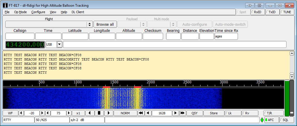
In DL-FLDIGI click Op Mode -> RTTY ->Custom.
Set carrier shift to 425, baud to 50, 7 bits per character, no parity and 2 stop bits. If everything is ok you should see DL-FLDIGI decoding the RTTY.
Getting started with the NTX2B and the Arduino – Part 3 DominoEX
RTTY as discussed in Part 2 of these articles uses two tones a high and a low tone to convey the data. Whilst simple its performance can degrade as the signal gets weaker and with no error correction you may get packets with errors in them. To mitigate a little against this there is a more robust mode called DominoEX.
Note : This example should work with the original NTX2 but you may get significant drift as the temperature changes which will change the tone spacing and mean this doesn’t work . The NTX2B with its TCXO is more suitable.
DominoEX is an MFSK (Multiple frequency-shift keying) mode that uses 18 tones to transmit data, although there is no error correction built in the performance of DominoEX is such that its rarely needed. If you can hear the signal generally you can decode it. For a more in depth description please visit this page : http://www.qsl.net/zl1bpu/MFSK/DEX.htm
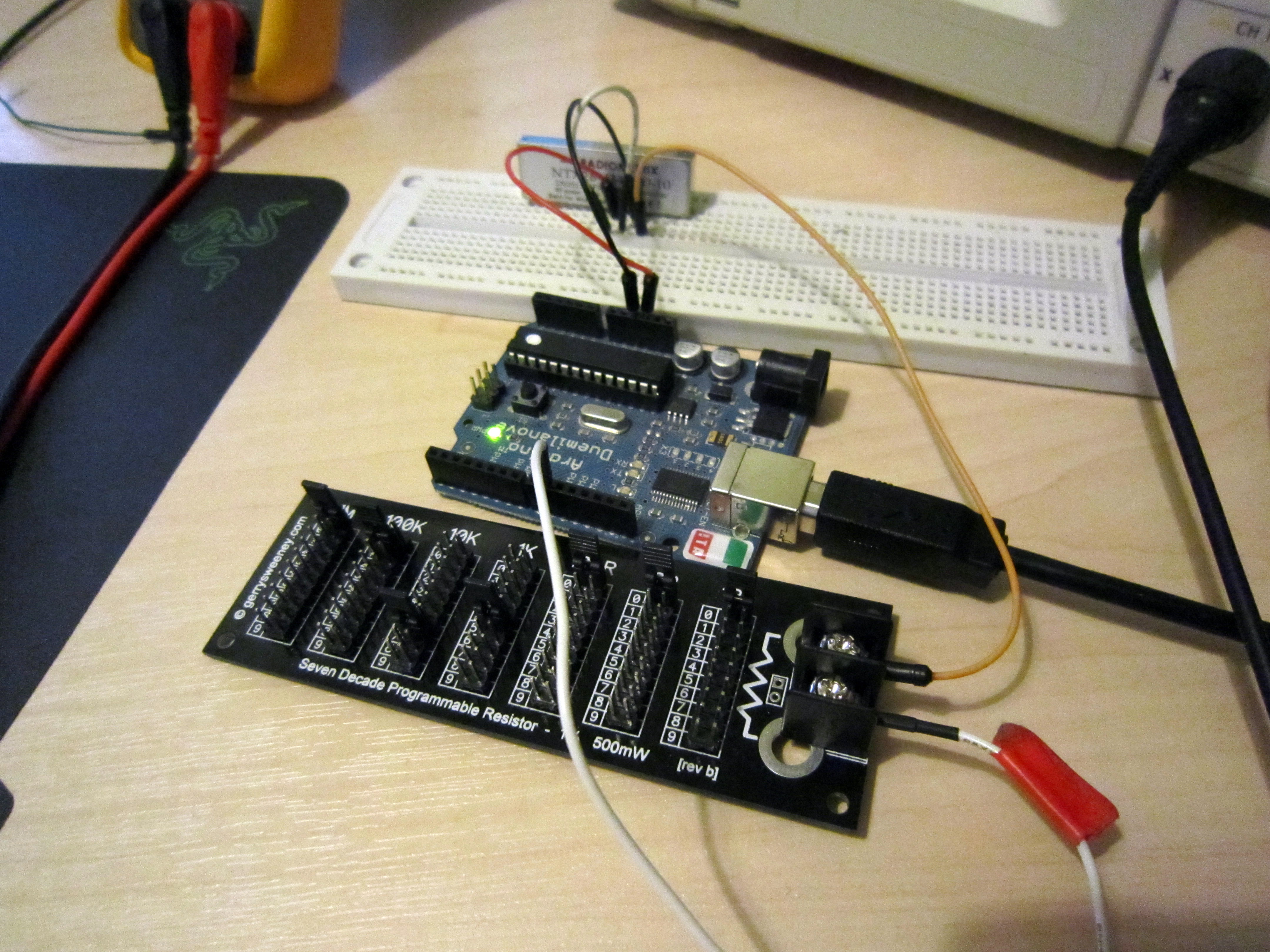
The key to DominoEX working is the distance between the tones has to be very precise. For DominoEX16 the baud rate has to be 15.625Hz. As you saw before our 8 bit Arduino doesn’t have the resolution to do this natively however we can increase the resolution of the Arduino by inserting a resistor between the Arduino pin 9 and the NTX2B TXD pin. The TXD pin has an internal 100k resistor so you’re making a voltage divider.
Using this method a 175k resistor means each PWM step gives the voltage needed to step the frequency up by the required amount. You may need to play with this to get the correct value. Here I’m using a Seven Decade Programmable resistor to test the values :
Code to test as follows :
|
1
2
3
4
5
6
7
8
9
10
11
12
13
14
15
16
17
18
19
20
21
22
23
24
25
26
27
28
29
30
31
32
33
34
35
36
37
38
39
40
41
42
43
44
45
46
47
48
49
50
51
52
53
54
55
56
57
58
59
60
61
62
63
64
65
66
67
68
69
70
71
72
73
74
75
76
77
78
79
80
81
82
83
84
85
86
87
88
89
90
91
92
93
94
95
96
97
98
99
100
101
102
103
104
105
106
107
108
109
110
111
112
113
114
115
116
117
118
119
120
121
122
123
124
125
126
127
128
129
130
131
132
133
134
135
136
137
138
139
140
141
142
143
144
145
146
147
148
149
150
151
152
153
154
155
156
157
158
159
160
161
162
163
164
165
166
167
168
169
170
|
/*Demo Code to Drive NTX2B via PWMDominoEXWritten by Anthony Stirk M0UPUThis example code is in the public domain.*/#define RADIOPIN 9unsigned char varicode[][3] = {/* Primary alphabet */{ 1,15, 9}, { 1,15,10}, { 1,15,11}, { 1,15,12}, { 1,15,13}, { 1,15,14}, { 1,15,15}, { 2, 8, 8},{ 2,12, 0}, { 2, 8, 9}, { 2, 8,10}, { 2, 8,11}, { 2, 8,12}, { 2,13, 0}, { 2, 8,13}, { 2, 8,14},{ 2, 8,15}, { 2, 9, 8}, { 2, 9, 9}, { 2, 9,10}, { 2, 9,11}, { 2, 9,12}, { 2, 9,13}, { 2, 9,14},{ 2, 9,15}, { 2,10, 8}, { 2,10, 9}, { 2,10,10}, { 2,10,11}, { 2,10,12}, { 2,10,13}, { 2,10,14},{ 0, 0, 0}, { 7,11, 0}, { 0, 8,14}, { 0,10,11}, { 0, 9,10}, { 0, 9, 9}, { 0, 8,15}, { 7,10, 0},{ 0, 8,12}, { 0, 8,11}, { 0, 9,13}, { 0, 8, 8}, { 2,11, 0}, { 7,14, 0}, { 7,13, 0}, { 0, 8, 9},{ 3,15, 0}, { 4,10, 0}, { 4,15, 0}, { 5, 9, 0}, { 6, 8, 0}, { 5,12, 0}, { 5,14, 0}, { 6,12, 0},{ 6,11, 0}, { 6,14, 0}, { 0, 8,10}, { 0, 8,13}, { 0,10, 8}, { 7,15, 0}, { 0, 9,15}, { 7,12, 0},{ 0, 9, 8}, { 3, 9, 0}, { 4,14, 0}, { 3,12, 0}, { 3,14, 0}, { 3, 8, 0}, { 4,12, 0}, { 5, 8, 0},{ 5,10, 0}, { 3,10, 0}, { 7, 8, 0}, { 6,10, 0}, { 4,11, 0}, { 4, 8, 0}, { 4,13, 0}, { 3,11, 0},{ 4, 9, 0}, { 6,15, 0}, { 3,13, 0}, { 2,15, 0}, { 2,14, 0}, { 5,11, 0}, { 6,13, 0}, { 5,13, 0},{ 5,15, 0}, { 6, 9, 0}, { 7, 9, 0}, { 0,10,14}, { 0,10, 9}, { 0,10,15}, { 0,10,10}, { 0, 9,12},{ 0, 9,11}, { 4, 0, 0}, { 1,11, 0}, { 0,12, 0}, { 0,11, 0}, { 1, 0, 0}, { 0,15, 0}, { 1, 9, 0},{ 0,10, 0}, { 5, 0, 0}, { 2,10, 0}, { 1,14, 0}, { 0, 9, 0}, { 0,14, 0}, { 6, 0, 0}, { 3, 0, 0},{ 1, 8, 0}, { 2, 8, 0}, { 7, 0, 0}, { 0, 8, 0}, { 2, 0, 0}, { 0,13, 0}, { 1,13, 0}, { 1,12, 0},{ 1,15, 0}, { 1,10, 0}, { 2, 9, 0}, { 0,10,12}, { 0, 9,14}, { 0,10,12}, { 0,11, 8}, { 2,10,15},{ 2,11, 8}, { 2,11, 9}, { 2,11,10}, { 2,11,11}, { 2,11,12}, { 2,11,13}, { 2,11,14}, { 2,11,15},{ 2,12, 8}, { 2,12, 9}, { 2,12,10}, { 2,12,11}, { 2,12,12}, { 2,12,13}, { 2,12,14}, { 2,12,15},{ 2,13, 8}, { 2,13, 9}, { 2,13,10}, { 2,13,11}, { 2,13,12}, { 2,13,13}, { 2,13,14}, { 2,13,15},{ 2,14, 8}, { 2,14, 9}, { 2,14,10}, { 2,14,11}, { 2,14,12}, { 2,14,13}, { 2,14,14}, { 2,14,15},{ 0,11, 9}, { 0,11,10}, { 0,11,11}, { 0,11,12}, { 0,11,13}, { 0,11,14}, { 0,11,15}, { 0,12, 8},{ 0,12, 9}, { 0,12,10}, { 0,12,11}, { 0,12,12}, { 0,12,13}, { 0,12,14}, { 0,12,15}, { 0,13, 8},{ 0,13, 9}, { 0,13,10}, { 0,13,11}, { 0,13,12}, { 0,13,13}, { 0,13,14}, { 0,13,15}, { 0,14, 8},{ 0,14, 9}, { 0,14,10}, { 0,14,11}, { 0,14,12}, { 0,14,13}, { 0,14,14}, { 0,14,15}, { 0,15, 8},{ 0,15, 9}, { 0,15,10}, { 0,15,11}, { 0,15,12}, { 0,15,13}, { 0,15,14}, { 0,15,15}, { 1, 8, 8},{ 1, 8, 9}, { 1, 8,10}, { 1, 8,11}, { 1, 8,12}, { 1, 8,13}, { 1, 8,14}, { 1, 8,15}, { 1, 9, 8},{ 1, 9, 9}, { 1, 9,10}, { 1, 9,11}, { 1, 9,12}, { 1, 9,13}, { 1, 9,14}, { 1, 9,15}, { 1,10, 8},{ 1,10, 9}, { 1,10,10}, { 1,10,11}, { 1,10,12}, { 1,10,13}, { 1,10,14}, { 1,10,15}, { 1,11, 8},{ 1,11, 9}, { 1,11,10}, { 1,11,11}, { 1,11,12}, { 1,11,13}, { 1,11,14}, { 1,11,15}, { 1,12, 8},{ 1,12, 9}, { 1,12,10}, { 1,12,11}, { 1,12,12}, { 1,12,13}, { 1,12,14}, { 1,12,15}, { 1,13, 8},{ 1,13, 9}, { 1,13,10}, { 1,13,11}, { 1,13,12}, { 1,13,13}, { 1,13,14}, { 1,13,15}, { 1,14, 8},{ 1,14, 9}, { 1,14,10}, { 1,14,11}, { 1,14,12}, { 1,14,13}, { 1,14,14}, { 1,14,15}, { 1,15, 8},/* Secondary alphabet */{ 6,15, 9}, { 6,15,10}, { 6,15,11}, { 6,15,12}, { 6,15,13}, { 6,15,14}, { 6,15,15}, { 7, 8, 8},{ 4,10,12}, { 7, 8, 9}, { 7, 8,10}, { 7, 8,11}, { 7, 8,12}, { 4,10,13}, { 7, 8,13}, { 7, 8,14},{ 7, 8,15}, { 7, 9, 8}, { 7, 9, 9}, { 7, 9,10}, { 7, 9,11}, { 7, 9,12}, { 7, 9,13}, { 7, 9,14},{ 7, 9,15}, { 7,10, 8}, { 7,10, 9}, { 7,10,10}, { 7,10,11}, { 7,10,12}, { 7,10,13}, { 7,10,14},{ 3, 8, 8}, { 4,15,11}, { 5, 8,14}, { 5,10,11}, { 5, 9,10}, { 5, 9, 9}, { 5, 8,15}, { 4,15,10},{ 5, 8,12}, { 5, 8,11}, { 5, 9,13}, { 5, 8, 8}, { 4,10,11}, { 4,15,14}, { 4,15,13}, { 5, 8, 9},{ 4,11,15}, { 4,12,10}, { 4,12,15}, { 4,13, 9}, { 4,14, 8}, { 4,13,12}, { 4,13,14}, { 4,14,12},{ 4,14,11}, { 4,14,14}, { 5, 8,10}, { 5, 8,13}, { 5,10, 8}, { 4,15,15}, { 5, 9,15}, { 4,15,12},{ 5, 9, 8}, { 4,11, 9}, { 4,12,14}, { 4,11,12}, { 4,11,14}, { 4,11, 8}, { 4,12,12}, { 4,13, 8},{ 4,13,10}, { 4,11,10}, { 4,15, 8}, { 4,14,10}, { 4,12,11}, { 4,12, 8}, { 4,12,13}, { 4,11,11},{ 4,12, 9}, { 4,14,15}, { 4,11,13}, { 4,10,15}, { 4,10,14}, { 4,13,11}, { 4,14,13}, { 4,13,13},{ 4,13,15}, { 4,14, 9}, { 4,15, 9}, { 5,10,14}, { 5,10, 9}, { 5,10,15}, { 5,10,10}, { 5, 9,12},{ 5, 9,11}, { 3, 8,12}, { 4, 9,11}, { 4, 8,12}, { 4, 8,11}, { 3, 8, 9}, { 4, 8,15}, { 4, 9, 9},{ 4, 8,10}, { 3, 8,13}, { 4,10,10}, { 4, 9,14}, { 4, 8, 9}, { 4, 8,14}, { 3, 8,14}, { 3, 8,11},{ 4, 9, 8}, { 4,10, 8}, { 3, 8,15}, { 4, 8, 8}, { 3, 8,10}, { 4, 8,13}, { 4, 9,13}, { 4, 9,12},{ 4, 9,15}, { 4, 9,10}, { 4,10, 9}, { 5,10,12}, { 5, 9,14}, { 5,10,12}, { 5,11, 8}, { 7,10,15},{ 7,11, 8}, { 7,11, 9}, { 7,11,10}, { 7,11,11}, { 7,11,12}, { 7,11,13}, { 7,11,14}, { 7,11,15},{ 7,12, 8}, { 7,12, 9}, { 7,12,10}, { 7,12,11}, { 7,12,12}, { 7,12,13}, { 7,12,14}, { 7,12,15},{ 7,13, 8}, { 7,13, 9}, { 7,13,10}, { 7,13,11}, { 7,13,12}, { 7,13,13}, { 7,13,14}, { 7,13,15},{ 7,14, 8}, { 7,14, 9}, { 7,14,10}, { 7,14,11}, { 7,14,12}, { 7,14,13}, { 7,14,14}, { 7,14,15},{ 5,11, 9}, { 5,11,10}, { 5,11,11}, { 5,11,12}, { 5,11,13}, { 5,11,14}, { 5,11,15}, { 5,12, 8},{ 5,12, 9}, { 5,12,10}, { 5,12,11}, { 5,12,12}, { 5,12,13}, { 5,12,14}, { 5,12,15}, { 5,13, 8},{ 5,13, 9}, { 5,13,10}, { 5,13,11}, { 5,13,12}, { 5,13,13}, { 5,13,14}, { 5,13,15}, { 5,14, 8},{ 5,14, 9}, { 5,14,10}, { 5,14,11}, { 5,14,12}, { 5,14,13}, { 5,14,14}, { 5,14,15}, { 5,15, 8},{ 5,15, 9}, { 5,15,10}, { 5,15,11}, { 5,15,12}, { 5,15,13}, { 5,15,14}, { 5,15,15}, { 6, 8, 8},{ 6, 8, 9}, { 6, 8,10}, { 6, 8,11}, { 6, 8,12}, { 6, 8,13}, { 6, 8,14}, { 6, 8,15}, { 6, 9, 8},{ 6, 9, 9}, { 6, 9,10}, { 6, 9,11}, { 6, 9,12}, { 6, 9,13}, { 6, 9,14}, { 6, 9,15}, { 6,10, 8},{ 6,10, 9}, { 6,10,10}, { 6,10,11}, { 6,10,12}, { 6,10,13}, { 6,10,14}, { 6,10,15}, { 6,11, 8},{ 6,11, 9}, { 6,11,10}, { 6,11,11}, { 6,11,12}, { 6,11,13}, { 6,11,14}, { 6,11,15}, { 6,12, 8},{ 6,12, 9}, { 6,12,10}, { 6,12,11}, { 6,12,12}, { 6,12,13}, { 6,12,14}, { 6,12,15}, { 6,13, 8},{ 6,13, 9}, { 6,13,10}, { 6,13,11}, { 6,13,12}, { 6,13,13}, { 6,13,14}, { 6,13,15}, { 6,14, 8},{ 6,14, 9}, { 6,14,10}, { 6,14,11}, { 6,14,12}, { 6,14,13}, { 6,14,14}, { 6,14,15}, { 6,15, 8},};uint8_t _sym = 0;void setup() {pinMode(RADIOPIN, OUTPUT);setPwmFrequency(RADIOPIN, 1);}// the loop routine runs over and over again forever:void loop() {dominoex_string("M0UPU DOMINOEX TEST\n");}void dominoex_txsym(uint8_t sym){_sym = (_sym + 2 + sym) % 18;analogWrite(RADIOPIN, _sym);delay(64);}void dominoex_txchar(uint16_t vcode){uint8_t i, c;for(i = 0; i < 3; i++){c = varicode[vcode][i];if(i && !(c & 0x8)) break;dominoex_txsym(c);}}void dominoex_string(char *s){for(; *s; s++) dominoex_txchar(*s);}void setPwmFrequency(int pin, int divisor) {byte mode;if(pin == 5 || pin == 6 || pin == 9 || pin == 10) {switch(divisor) {case 1:mode = 0x01;break;case 8:mode = 0x02;break;case 64:mode = 0x03;break;case 256:mode = 0x04;break;case 1024:mode = 0x05;break;default:return;}if(pin == 5 || pin == 6) {TCCR0B = TCCR0B & 0b11111000 | mode;}else {TCCR1B = TCCR1B & 0b11111000 | mode;}}else if(pin == 3 || pin == 11) {switch(divisor) {case 1:mode = 0x01;break;case 8:mode = 0x02;break;case 32:mode = 0x03;break;case 64:mode = 0x04;break;case 128:mode = 0x05;break;case 256:mode = 0x06;break;case 1024:mode = 0x7;break;default:return;}TCCR2B = TCCR2B & 0b11111000 | mode;}} |
Viewed in DL-FLDIGI (Click Op Mode -> DominoEX -> DominoEX16)
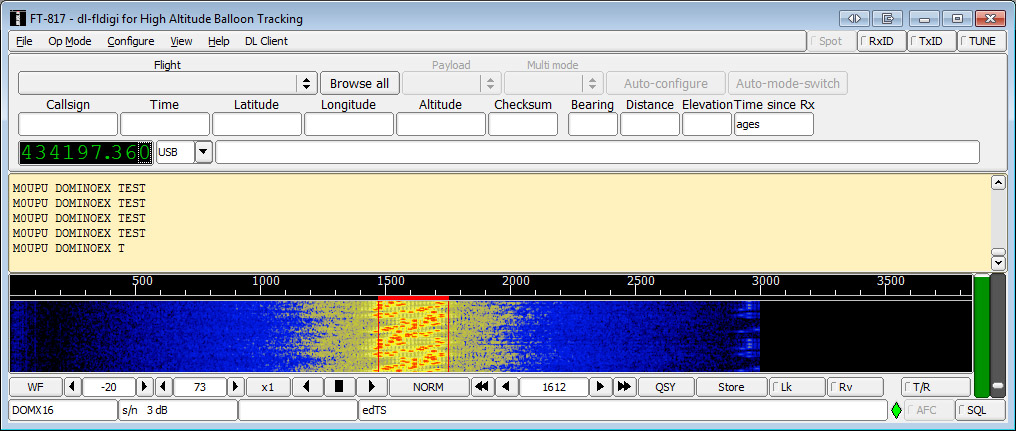
You can adjust the code to do DominoEX22 by amending the delay line from 64 ( 1/Baud rate so for DominoEX16 = 0.064s, DominoEX22 = 1/21.533 = 0.0464) to 46 and adjusting the resistor to ~ 100k.
You can purchase the NTX2B at Hab Supplies here : http://ava.upuaut.net/store/index.php?route=product/product&path=71_63&product_id=92
Zdroj :
Getting started with the NTX2B and the Arduino – Part 1 The Basics
Getting started with the NTX2B and the Arduino – Part 2 RTTY
Getting started with the NTX2B and the Arduino – Part 3 DominoEX
Social Profiles